As equipment powered by industrial belts become smaller, in electric vehicles and other applications, how does Clavis ensure its belt measurement device perfectly fit our customers’ production environments — particularly when they are located hundreds-of-thousands of miles away? In my latest blog, I explain why computer aided design (CAD) is vital to Clavis’s unique production and services, and to helping you get the best belt measurement on your production line.
One of the first uses of CAD was in 1957 at General Motors Research Laboratories. The lab was equipped with a Design Automated by Computer (DAC) developed by American computer scientist Patrick Hanratty. It is thought to be the first CAD and computer aided manufacturing (CAM) system involving interactive graphics. Today, Hanratty is known as the father of CAD/CAM.
CAD and CAM are essential to what we do at Clavis. For pretty much all our projects, we supply belt tension measuring equipment, handbrake measurement systems and more that are required to fit seamlessly into our customers’ production set-ups — whether they produce automotive systems, agricultural equipment, mobile refrigeration systems or 3D printers.
“The customer will send us a CAD schematic of an engine block with most of the components we don’t need to see removed — or our own designer can remove them — and just the essential components left, like the belt and pulleys.”
Because our customers are all around the world — in the US, China and elsewhere — we have to make judgements remotely, with the utmost accuracy! This was certainly the case during the pandemic in cases where travel was out of the question. And it especially applies to our range of customised sensor heads with mounting units, either optical or acoustic. To achieve an accurate measurement, a belt must be measured at the “right spot”.

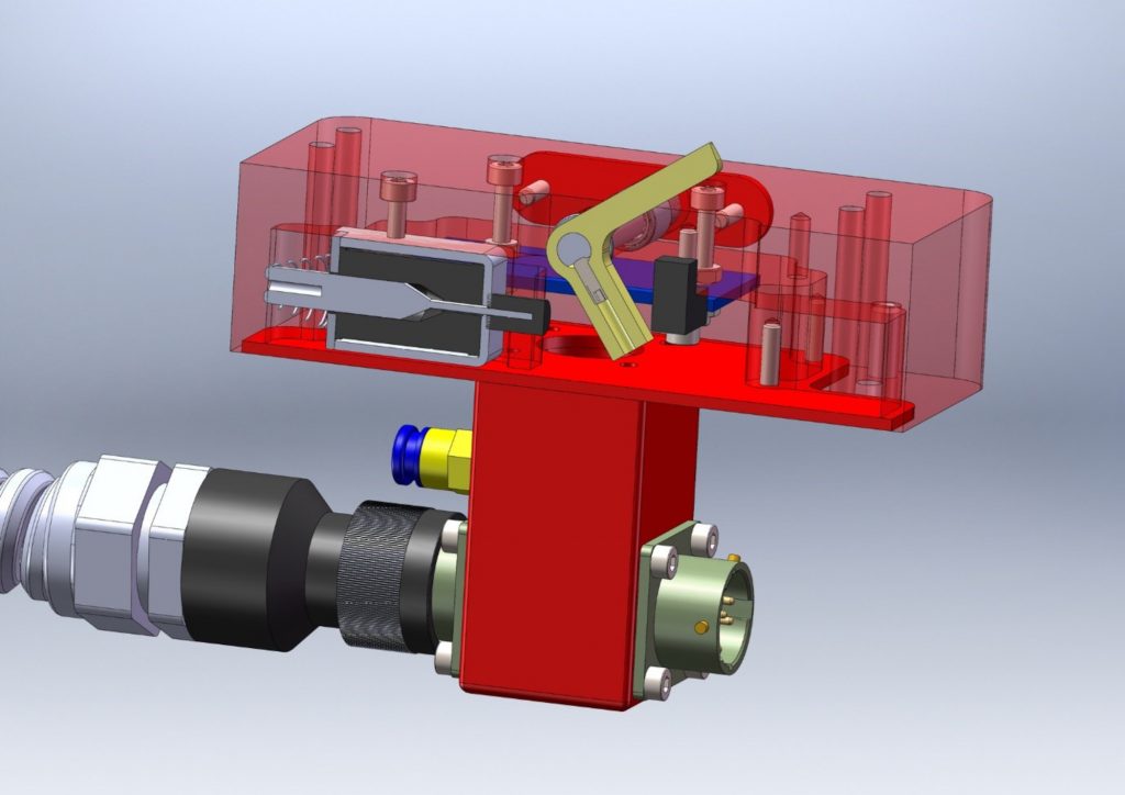
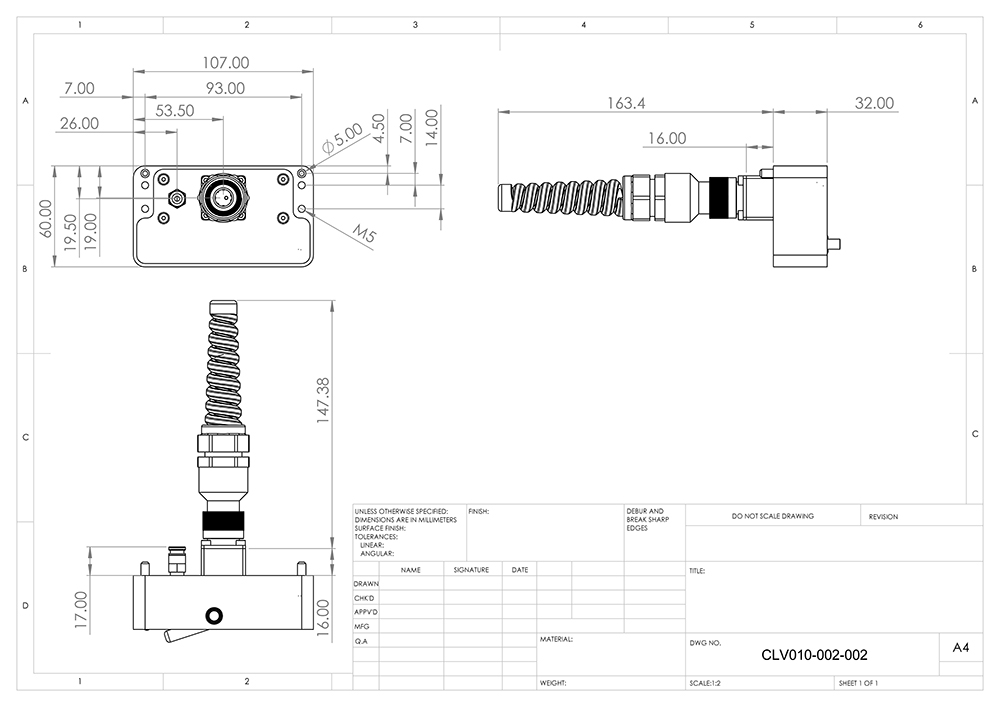
With Clavis’s customised sensor heads, the shape of the aluminium housing is designed specifically to reach the ideal spot on the belt, wherever it may be — the customer may have a small engine block design, for instance. Generally, the trend at the moment is towards smaller belts, whether they are in electric vehicle engines, electric power assisted steering (EPAS) or elsewhere. Our challenge is to shrink everything down, including the sensor head.
Collaborating remotely
To begin, a customer will normally send us camera phone images of the unit, but there’s only so much information you can glean from a few pictures. Aside from the CAD drawing, we try to get the physical part — say, an engine block — onsite so we can physically test our gear inside it. Otherwise, understanding the dimensions of the rig is where CAD design comes into play.


The customer will send us a CAD schematic of an engine block with most of the components we don’t need to see removed — or our own designer can remove them — and just the essential components left, like the belt and pulleys. With CAD, we can determine the necessary size and shape of the sensor head for their requirements. A sensor head design can evolve from a simple block to a unique-shaped device that will theoretically fit perfectly into the nooks and crannies of the customer’s engine block.
Aside from looking at the customers’ supplied CAD drawing, our designer must put themselves in the operator’s shoes and ask several practical questions. How high is the unit off the ground? Every new project presents its own challenges, and space is always one — are there other objects or equipment around the unit can restrict the access to the belt? Space within, say, an engine unit where the belt is located can often be a nightmare to get to!
What’s more, on any production line, the operator may be measuring the tension of hundreds of industrial belts each day. Easy application and remove is utterly essential here — if they operator experiences any problems adding or removing the tool then they might not use it.
“The trend at the moment is towards smaller belts, whether they are in electric vehicle engines, electric power assisted steering (EPAS) or elsewhere. Our challenge is to shrink everything down, including the sensor head.”
Fortunately, David, our CAD specialist, is also an experienced mechanical engineer — and a petrolhead, which helps with our automotive customers! Having experience of running CNC machines and lathes is certainly helpful. In short, our design processes are informed by real-life experience of the machine shop, including how it will complement the customer’s manufacturing and production line. It’s the full cycle of design — during which our CAD designer will consult the customer’s machine shop, the electric and R&D section to make sure the design is just right.
Perfecting the design
The final design stage for our products will be to visit the customers’ production facility and apply the sensor head to their unit, in real-life. This will sometimes necessitate final design tweaks, then we can proceed with manufacturing the customer’s bespoke sensor head.
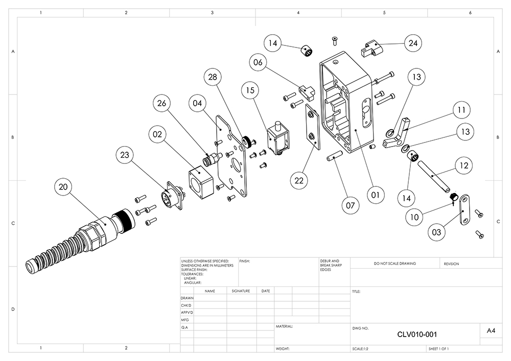
At Clavis, we manufacture everything in-house except for the printed circuit boards. Once we have a design finalised with our customer, we can then process with manufacturing the final bespoke sensor head. There’s always the challenge of making the sensor head small enough, while factoring in the electronics and aluminium casing. CAD drawings also allow us to produce exploded diagrams for our customers, which specifies and lists the parts needed in their specific belt measurement devices.
While CAD allows us to produce bespoke solutions for our customers in the present, in the future we may see a growing requirement for custom sensor heads as tomorrow’s electric vehicles evolve through different designs. Things have come a long way since Patrick Hanratty’s 1950s DAC machine — and we’ll continue to evolve our products to meet tomorrow’s requirements.
Article by Andrew Punton

